Search
News
Welcome to the News Articles, your gateway to thousands of insights, reports, and stories published across a wide range of topics. This section serves as the archive and central access point for all articles available on FindArticles.com.
Our coverage spans multiple areas of interest, ensuring that readers, researchers, and professionals can easily discover the content they need. Explore the sub-categories below:
Technology
Stay up to date with developments in software, hardware, innovation, and the digital economy. From breakthrough research to industry shifts, our technology section brings you articles that track the fast pace of change.
Business
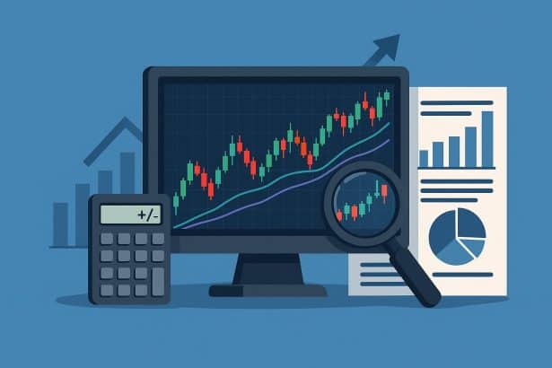
Covering markets, companies, finance, and entrepreneurship, the business archive highlights case studies, analysis, and trends that shape the global economy.
Entertainment
Dive into culture, film, music, books, and more. Entertainment articles feature reviews, commentary, and reporting on the creative industries.
Science & Health
Explore scientific discoveries, medical research, health advice, and environmental studies. This section offers a mix of academic reporting and practical insights.