


Fabricators moving from MIG or TIG to laser welding often report the same surprise. The machine works well on clean test coupons and then behaves unpredictably on real parts. In most cases the equipment is not the problem. The joint is.
A laser concentrates energy into a much smaller area than an arc, which changes how much preparation error the process will tolerate. A gap that a MIG welder would simply fill with more wire can leave a laser beam passing straight through. Getting consistent results from a handheld laser welder therefore depends heavily on fit-up, clamping, and surface condition — factors that sit upstream of the welding operation entirely.
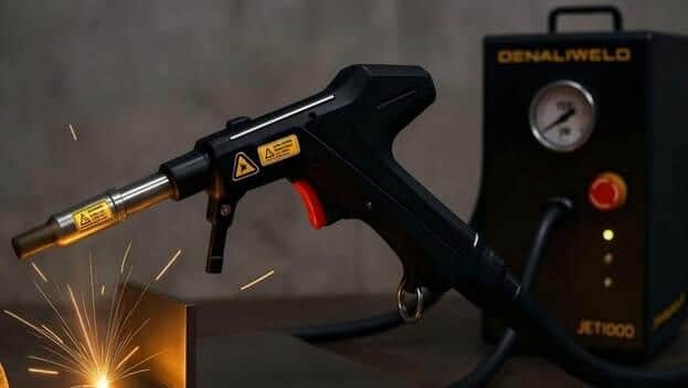
Why Laser Welding Is Less Forgiving of Gaps
The practical difference comes down to how the heat is delivered.
An arc process deposits filler metal across a relatively wide area. If the joint opens up, the operator can weave, slow down, and add material until the gap is bridged. The heat input rises and some distortion follows, but the joint closes.
Laser welding works differently. The beam is focused to a small spot, and in autogenous welding there is no filler metal at all. The process relies on melting the two edges and letting them fuse. When the edges are not close enough to melt into one another, there is nothing to bridge the space. The result is a weld that looks acceptable on the surface but has little or no root fusion, or a beam that cuts rather than joins.
This is why joint preparation deserves more attention with laser than with arc work. The various welding joint configurations — butt, lap, corner, tee, and edge — each behave differently under a concentrated beam, and some are considerably more tolerant than others.
Which Joint Types Handle Laser Welding Best
Not every joint design is equally suited to a focused beam.
Lap joints are generally the most forgiving. The two sheets overlap, so there is material behind the beam and small positioning errors are absorbed. For thin sheet work, this is often the first choice.
Butt joints demand the tightest fit-up. The edges must sit close and stay close along the whole seam, because there is nothing behind the joint to catch the beam. Any variation in the cut edge shows up directly in the weld.
Corner and tee joints sit in between. They provide a natural seam for the beam to follow, which helps with tracking, but the fit at the root still governs penetration.
Edge joints on thin material can work well because the beam has material on both sides, though burn-through becomes a risk if power and travel speed are not matched to the thickness.
The practical takeaway is that joint selection is part of the welding decision, not something fixed by the drawing. Where a design allows a choice between a butt and a lap joint, the lap configuration will usually be easier to run consistently.
Preparing the Edges Before Welding
Surface and edge condition matter more than most operators expect.
Laser energy is absorbed differently by clean metal, oxidised metal, oil, and coatings. Mill scale, paint, cutting fluid, and galvanising can all change how the beam couples into the surface, and inconsistent coating means inconsistent absorption along a single seam. Cleaning the joint area is not a cosmetic step.
Cut quality is the other factor. A plasma or oxy-fuel cut edge with visible dross and a variable profile will produce a variable gap when two parts are brought together. Laser-cut, sawn, or machined edges give a far more consistent starting point. Where rough-cut parts have to be used, dressing the edges before assembly is usually faster than fighting the weld afterwards.
Tack welding also deserves thought. Tacks placed too far apart allow the joint to open between them as heat is applied. Closer tacks, or a fixture that holds the joint along its length, keep the gap stable while the seam is being welded.
Clamping and Fixturing to Hold the Gap
Fixturing is where most fit-up problems are actually solved.
A clamp arrangement that was adequate for arc welding may allow enough movement to affect a laser weld, because the tolerance band is narrower. The requirement is not simply to hold the parts together but to hold them in the same relative position along the entire seam while the metal expands and contracts.
Points worth checking:
- Clamping close to the joint rather than at the part extremities
- Support underneath the seam on thin sheet to prevent sagging
- Backing bars where root support or heat sinking would help
- Repeatable locating features so the part sits the same way every time
- Clear access for the welding head without the fixture blocking the approach angle
For repeat production, a dedicated fixture usually pays for itself quickly. For varied one-off work, a modular clamping setup with reliable locating points is a reasonable compromise.
Using Filler Wire to Bridge Gaps
Filler wire is the practical answer when a gap cannot be eliminated.
Adding wire gives the process material to work with, which extends the range of gap the joint can tolerate and helps produce a fuller weld profile. It also allows a small crown on the joint where the design calls for it. Many handheld systems support automatic wire feeding across a range of common diameters, and matching the wire size to the material, thickness, and gap is part of setting up the job.
Filler wire is not a substitute for preparation, though. It widens the tolerance band rather than removing the need for one, and feeding wire into an excessive gap tends to produce an irregular bead with uneven penetration.
Fit-Up Reference by Joint Type
| Joint type | Gap tolerance | Typical use | Main risk |
|---|---|---|---|
| Lap | Most forgiving | Thin sheet, panel assembly | Trapped contamination between sheets |
| Butt | Tightest requirement | Visible seams, flush joints | Lack of root fusion, beam pass-through |
| Corner | Moderate | Enclosures, frames | Root fit governs penetration |
| Tee | Moderate | Structural and bracket work | Access angle for the head |
| Edge | Moderate on thin material | Flanged thin sheet | Burn-through if power is too high |
Building Fit-Up Into the Process
The most reliable improvement is usually procedural rather than technical.
Define an acceptable gap for each recurring job and check it before welding rather than after. Record the joint type, fixture used, and filler wire size alongside the welding parameters, so the whole setup is repeatable and not just the machine settings. Where a job consistently gives trouble, look at the cutting and assembly stages before adjusting power.
Denaliweld supplies handheld and automated laser welding equipment with wire-feeding options across several wire diameters, and reviewing the available systems alongside your typical joint designs and material thicknesses gives a more useful comparison than power ratings on their own.
Conclusion
Handheld laser welding rewards preparation. The concentrated beam that produces narrow, clean welds with low distortion is the same characteristic that makes the process sensitive to gaps, contamination, and part movement.
Choose the joint design with the process in mind, clean and dress the edges, clamp close to the seam, and add filler wire where a gap cannot be closed mechanically. Most weld quality problems attributed to a handheld laser system turn out to originate before the trigger is pulled.